Hardware interface
Help on how to establish an interface between various hardware components, for example:
- synchronize the virtual reality (VR) with a microscope
- trigger optogenetic stimulation,
- read in positional updates from a treadmill tracking system (Fictrac)
Our VR setups consisted of a spherical treadmill and a panoramic screen in addition to the VR software. For further information on how to design a polygonal, projector-based display, see Display. On this page, you will find information on how to use FicTrac and a National Instruments (NIDaq) board together with the Janelia Unity Toolkit VR. There is some degree of flexibility to accommodate different hardware configurations compared to the onese described here.
Table of contents
Closed-loop updates of the animals virtual position
We use a spherical treadmill for tracking walking behavior as described in detail in (Seelig et al., 2010). The ball was machine-cut from polyurethane foam (FR-7110, Last-A-Foam, General Plastics Manufacturing Company, Tacoma, WA, USA), weighted about 50 mg, and had a diameter of about 9 mm. The ball was resting on an air cushion maintained by a constant air flow (0.55 l/min, controlled with a mass flow controller by Alicat Scientific, Tucson, AZ, USA) to ensure low-friction rotations.
To capture ball rotations created by the animal’s walking maneuvres, we use FicTrac (Moore et al., 2014). FicTrac is an open-source, video-based ball tracking system. Full documentation for how to set up and use FicTrac can be found on their website. We set up FicTrac to send the output to a socket port, where it could be read out by the VR software.
Tracking camera
We illuminated the ball in infrared and used a high-speed camera (Grasshopper3 GS3-U3-23S6M, 2.3 MP, Teledyne FLIR, Wilsonville, OR, USA) to film the ball at a slightly higher frame rate than the intended frame rate of the VR system (the frame rate of the display). In our hands, a frame rate of 150 Hz worked well, but higher frame rates occasionally caused delays in the image processing and consequently in delayed VR updates. As an alternative, cheeper camera we recommend Basler dart M dmA1440-73gm (Mono). As a cost-effective lense, we recommend Raspberry Pi SC0123.
For the illumination of the ball, IR LEDs with custom wiring work well:
- 2 X 850 nm, focused LEDs: LED851L from ThorLabs
- 1 x LED controller: SLA-100-2 from Mightex The LEDs should be wired in series so that they both received the same amount of current. They were mounted to rail carriages with stiff wire so that they were in line with the cameras, and adjusted so that they sat below the camera line of sight and pointing up, illuminating the ball centre.
Treadmill ball
For the ball we use polyurethane foam from general plastics’ LAST-A-FOAM FR 7100 series. This product series includes foams of different densities. The density of the foam affects the ball weight and inertia and as a consequence the fly’s walking behaviour. We have primarily used FR-7120 (20 lbs/ft3) and FR-7110 (10 lbs/ft3). We use the higher density material for the smaller balls (6 mm) and the lower density material for larger balls (8-9 mm).
Tracking with FicTrac requires the ball surface to be patterned such that there is a unique pattern for each orientation. We painted high-contrast patterns on the ball with black acrylic paint on a red base coat (Premiere Acrylic Colour, Laurel, NJ, USA). This coat of acrylic paint also helped to reduce noise from the ball during calcium imaging.
Fictrac settings
Fictrac settings are saved in a config file, which is passed to FicTrac via the command line when starting the application. Most settings will be set through the configuration routine. However, some settings have to be manually added or edited. A full list of the parameters and explanations can be found here.Below is an explanation of what we found to be important.
- vfov: vertical FOV of the input images in degrees. You can estimate this by measuring the distance of the camera to the ball and the height of the image at the ball (ruler in camera view). For example: distance = 16 cm, height = 0.9 cm → ~3.22 degree (empirically 3.35 worked well for us)
- q_factor: 4. Adjusts the resolution of the tracking window. Smaller values correspond to coarser but quicker tracking and vice-versa. Normally in the range [3,10].
- src_fn: 0 for streaming incoming video
- do_display: should be FALSE for settings used with Unity, but TRUE during debugging
- sock_port: can be added to set socket port number for streaming tracking data to socket. This is used to feed tracking data into Unity. I use socket port 2000.
- Alternatively, one could transmit data via comport (com_port -> set string, com_baud → set baud rate (int), default is 115200)
Note: for some reason the ball radius seems to reset when manually editing the config file. Quickly go through the configuration procedure to reset.
An example settings file can be found here.
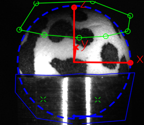
The camera’s reference frame is defined as:
- X = image right (cols);
- Y = image down (rows);
- Z = into image (out from camera)
The animal’s reference frame is defined as:
- X = forward
- Y = right
- Z = down
Interface with a NIDaq board
We have used the following data acquisition board from National Instruments:
- 781005-01 NI USB-6218 BNC BUS-POWERED M SE
- USB-6002
- USB-6009
An example for how to use the Unity-NIDaq interface can be found in the talk2NiDaqMx.cs script here.