Instructions for installing an external light source
Table of contents
The modification instructions below are for the DLPDLCR2010EVM model by Texas Instuments. Some of the steps might be applicable to other models, other steps might require extensive adjustments.
Parts should be printed with an SLA, MJF or SLS printer. If needed there are online printing services.
A modification guide for the DLP LightCrafter Display 3010EVM-G2 (TI DLPDLC3010EVM-G2) can be found here. It includes the following custom-designed 3D printed parts:
Disassembly
First, make sure all power is disconnected and you are properly grounded to prevent damaging components. It is advisable to retain all screws, components, and hardware as some will be reused in the new configuration.
- Remove the 2 screws holding the optical engine mounting plate. Gently invert the plate.

- Disconnect the two LED ribbon cables either from the optical engine or the small circuit board.

- Gently pry the gold ribbon cable from the main circuit board.

- Remove the screws/nuts holding the optical engine to the plate and save them for a later step.
- Pry off the LED assembly from the opposite side of the ribbon cable. The front LED assembly can be left in place.

- Remove the projector circuit board assembly from the base plate. Retain the 5 M3 screws for a later step.

- Disassembly complete. For modification you will need the optical engine, circuit board and fasteners mentioned above.

Reassembly and modifications

Projector modifications
Commercial parts
- 1x Silver first surface mirror
- 3x 18mm M3 pan head screws
- 3x 6mm M3 pan head screws
- 3x #4-40 nuts
- 2x #00-96 screws
- VHB tape
3d printed parts (per projector)
- 1x PROJECTOR MOUNT FOR ADJ XY LLG
- 1x PROJECTOR LIGHTBLOCK (Optional, simpler methods for blocking board LEDs exist)
- 1x FLYVR PIVOT MOUNTPLATE
- 1x CORNER FLYVR PIVOT MOUNTPLATE (Optional, helpful if space is limited)
Modification steps
- Prepare the PROJECTOR MOUNT FOR ADJ XY LLG for assembly by using the #00-96 screws to cut threads into the printed holes and tap the hole on the vertical face for a #4-40 screw.

- Place the optical engine and ribbon cables onto the PROJECTOR MOUNT FOR ADJ XY LLG and secure with the screw from disassembly step #4.

- Carefully connect the ribbon cable from the optical engine to the circuit board.

- Gently fold the assembly over the circuit board and secure with 3 18mm M3 pan heads.

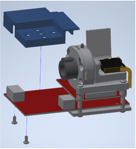
- Place the FLYVR PIVOT MOUNTPLATE, secure with the M3 screws from disassembly step #6

Liquid Light Guide Alignment Sub-Assembly
This allows for fine adjustment of the XY position of your light source relative to the optical engine.
Commercial parts Note that quantities are listed per projector assembly.
- 4x 4-40 flat head screws 0.375in
- 4x 4-40 flat head screws 0.625in
- 2x compression springs part # 70500
- 2x ultra fine threaded brass inserts
- 2x ultra fine threaded M3 set screws
- 1x 4-40 nylon tipped set screw
- 1x Thorlabs KM100 mount
- 1x Thorlabs post
- 1x Thorlabs post holder
- 1x Liquid Light Guide: LLG5-6H - Liquid Light Guide, Ø5 mm Core, 340 - 800 nm
3d Printed Parts These should be printed on a resin or polyjet printer for accuracy.
Liquid light guide alignment fabrication
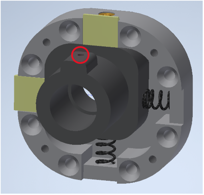
- Press the ultra-fine threaded brass inserts into the XY SLIDE BOTTOM until their flanges are against the inner wall. At this point the circled holes should be tapped for #4-40 screws.
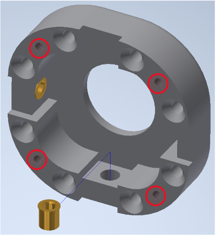
- Install the compression springs in the recesses opposite the inserts. A small dab of epoxy or superglue can be used to secure the base of the spring in the recess.
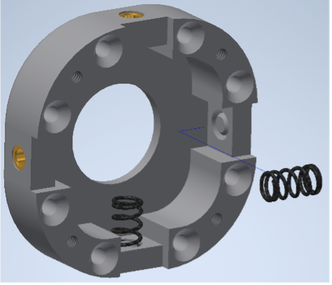
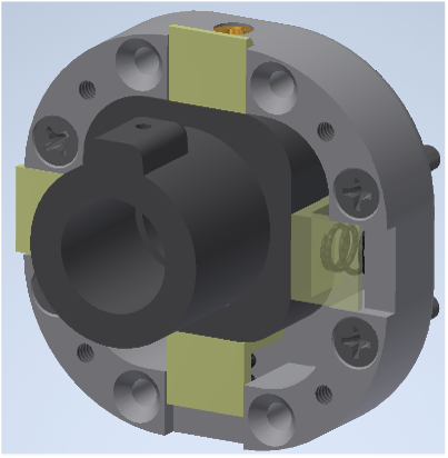
- Tap the hole in the XY SLIDE PLATE for a #4-40 set screw. Apply a small amount of oil to the base and sides of the XY SLIDE PLATE. Place it into the base along with 2 LINEAR GUIDE BLOCKS adjacent to the brass inserts.
-
With tweezers compress the springs and slip the remaining LINEAR GUIDE BLOCKS into place.
-
Insert 4x 0.625in #4-40 screws into the countersunk holes. The orientation of the assembly can be changed per projector to allow for easier access to the ultrafine set screws.
-
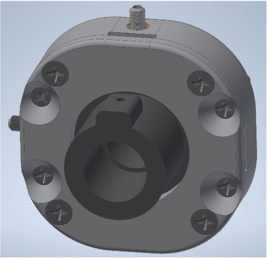
Place the XY SLIDE TOP onto the assembly and secure with 4x 0.375in #4-40 screws.
-
Insert ultrafine set screws into brass inserts. Adjust until the XY SLIDE PLATE is roughly centered.
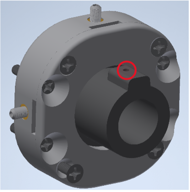
- Install the nylon tipped #4-40 set screw in the XY SLIDE PLATE.
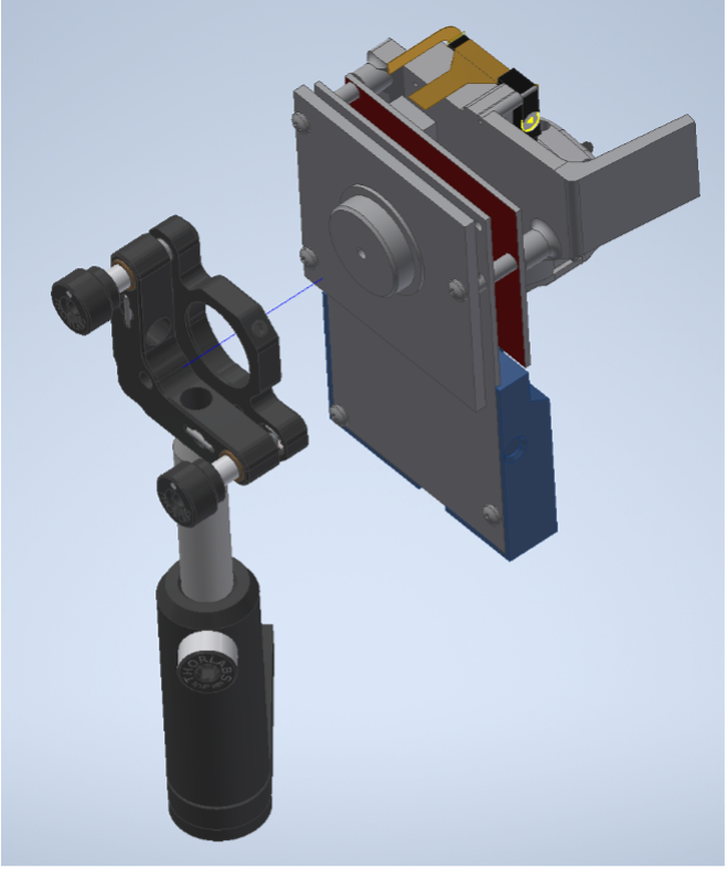
Joining the Sub-Assemblies
- Insert 3 #4-40 nuts into the vertical plate on the PROJECTOR MOUNT FOR ADJ XY LLG and secure the LLGA sub assembly via the #4-40 screws.
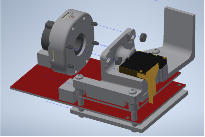
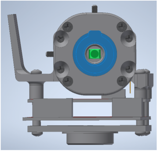
- Sight down the barrel of the LLG adapter and adjust the ultra-fine set screws until it is aligned with the LED lens assembly in the optical engine.
- Place the PROJECTOR LIGHTBLOCK and secure with an M3 screw from disassembly step #6
- Attach projector assembly to the thorlab KM100 and post.