Panoramic screen with 2, 3 or 4 projectors
Table of contents
Overview of the display design
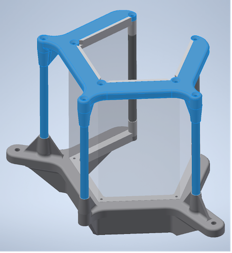
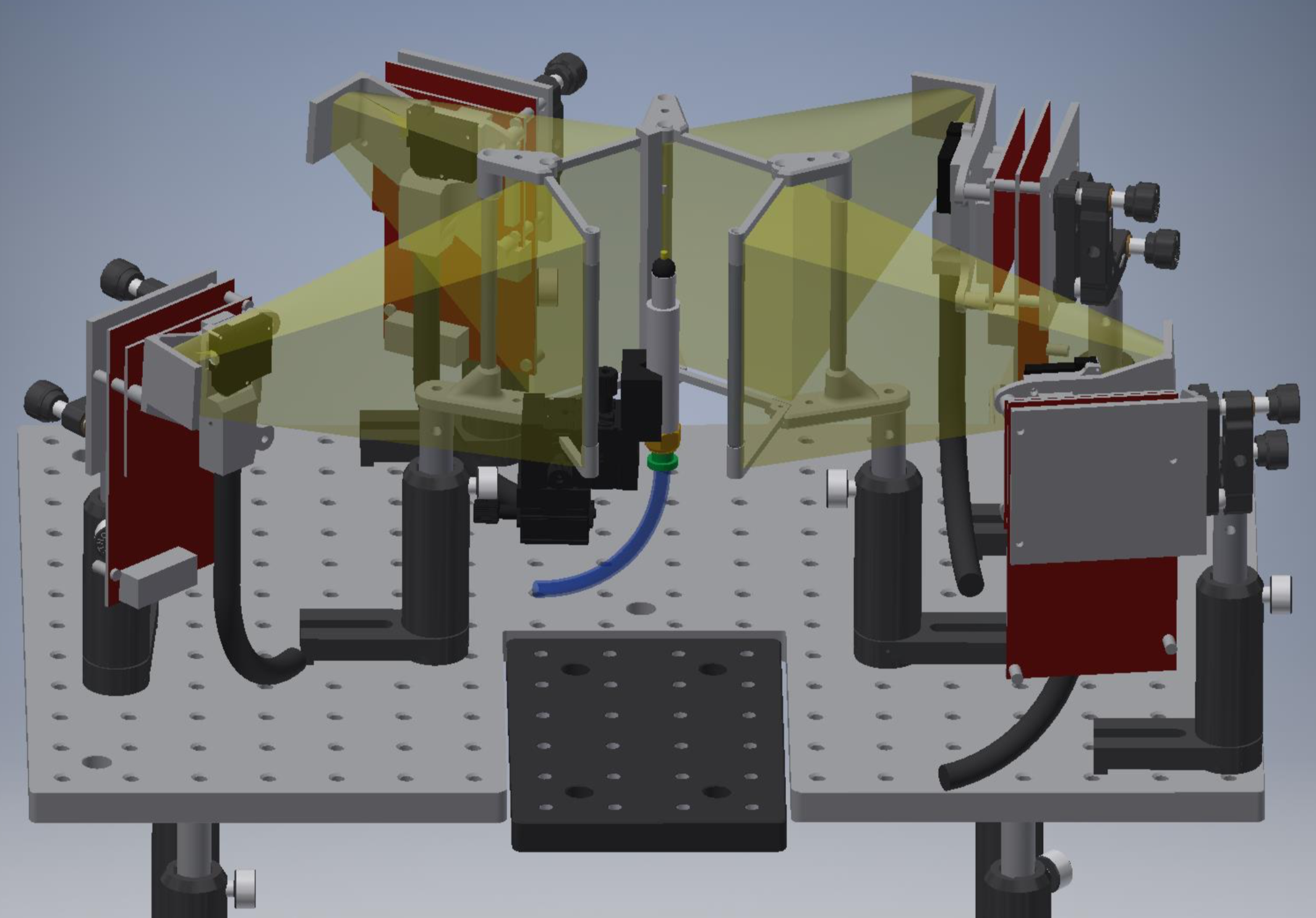
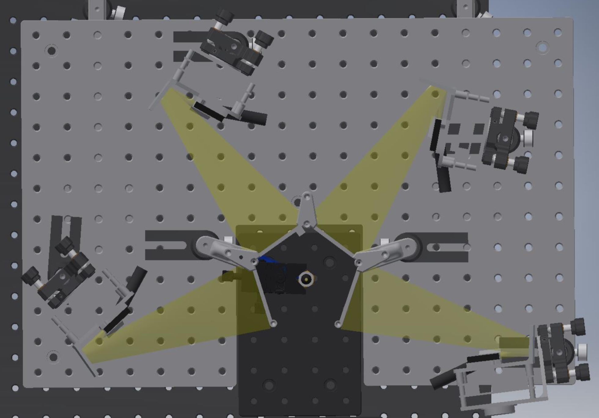
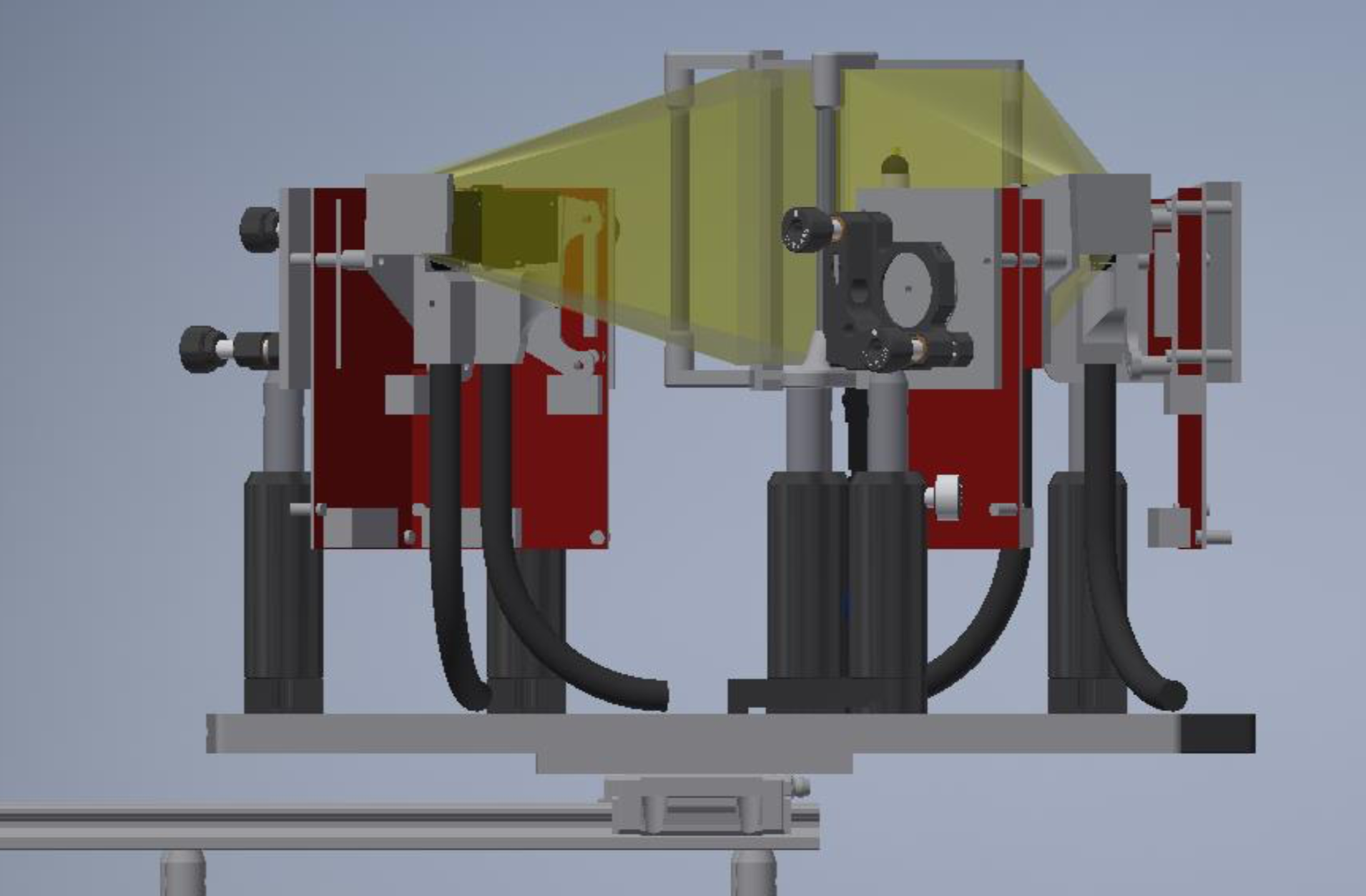
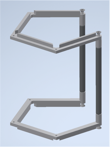
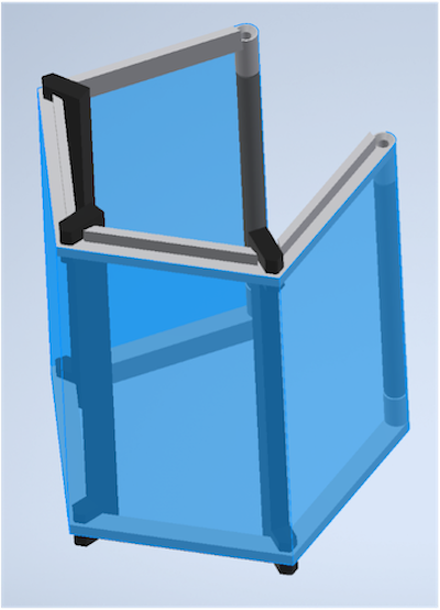
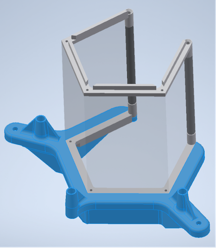
Below are renderings of a pentagonal panoramic display with four projectors. The projectors are mounted in a fixed position relative to the screen, such that alignment only needs to happen once (ideally). The full setup (screen + projectors) are mounted on a movable stage such that they can be moved out of the way to make the ball and fly easily accessible and give space to potential other rig components (e.g. a feeding station). With the two-projector desgin the movable stage is optional, as the ball and fly are more easily accessible through the open back.
Note: It is of course also possible to use computer monitors or any other device that can be set up as an extended display, instead of projectors. Here we focus on projector-based displays as most people are less familiar with this option and because projector-displays have some advantages: they are easily customizable for different wavelengths, can be modified to run monochromatically for frame packing and thus are convenient when used inside an imaging rig.
Parts list
2-projector screen
Commercial parts
3D printed parts Use an SLA, MJF or SLS printer.
- 2x 3d printed screen holder parts with holes tapped for 4-40 thread
- 3x screen assembly guide (printed or lasercut and used during assembly only)
- 1x Bottom Screen Support Frame
- 1x Top Screen Support Frame
Lasercut parts
- 1x fly holder centering aid: This helps with positioning the screen in a way that it is centered around the fly/ball holder.
3-projector screen
Commercial parts
3D printed parts Use an SLA, MJF or SLS printer.
- 2x 3d printed screen holder parts with holes tapped for 4-40 thread
- 2x screen assembly guide (3d printed or lasercut and used during assembly only)
- 1x Bottom Screen Support Frame
- 1x Top Screen Support Frame
Lasercut parts
- 1x fly holder centering aid: This helps with positioning the screen in a way that it is centered around the fly/ball holder.
4-projector screen
Commercial parts
3D printed parts Use an SLA, MJF or SLS printer.
- 2x 3d printed screen holder parts with holes tapped for 4-40 thread
- 3x screen assembly guide (printed or lasercut and used during assembly only)
- 1x Bottom Screen Support Frame
- 1x Top Screen Support Frame
Lasercut parts
- 1x fly holder centering aid: This helps with positioning the screen in a way that it is centered around the fly/ball holder.
All screen geometries
Screen material 1x precut screen sheet. For the diffuser sheet, we recommend Item # V-H105-CV07 or V-HHDE-PM06-S01-D01 from BrightView Technologies (Durham, NC, USA).
Screen dimensions: See here for 4-sided screen. To allow for a good fit, we recommend cutting the height to 3 15/16 inch. For the width, use 2.3 inch per face.
Projectors Recommendations for projectors are listed [here].
Screen assembly
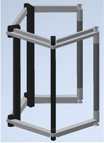
Below the assembly is shown for 4-projector screen. It works very similar for the other two screen geometries.
- Assemble the wide screen holders and 2 thorlabs MSR3 posts with the 4-40 screws.
- Re-enforce the assembly with the screen assembly guides (slip fit, no glue).
- Pre-crease the screen and carefully to align it to the frame. Use superglue to adhere the centermost fold to the frame top and bottom being careful to maintain tension and alignment. Once dry, glue from the center out around the frame again. Be careful with the alignment to prevent bowing or wrinkles. Use binder clips to temporarily clamp the screen to the frame.
- After everything has dried, remove the assembly guides, trim the screen flush top and bottom and screw this sub assembly into the Bottom Screen Support Frame with 3 #4-40 0.1875” screws.
- Place the top screen support and remaining posts and screw down with remaining #4-40 screws (0.3125in) into screen frame, 0.75in into the thorlabs posts.